new test rig
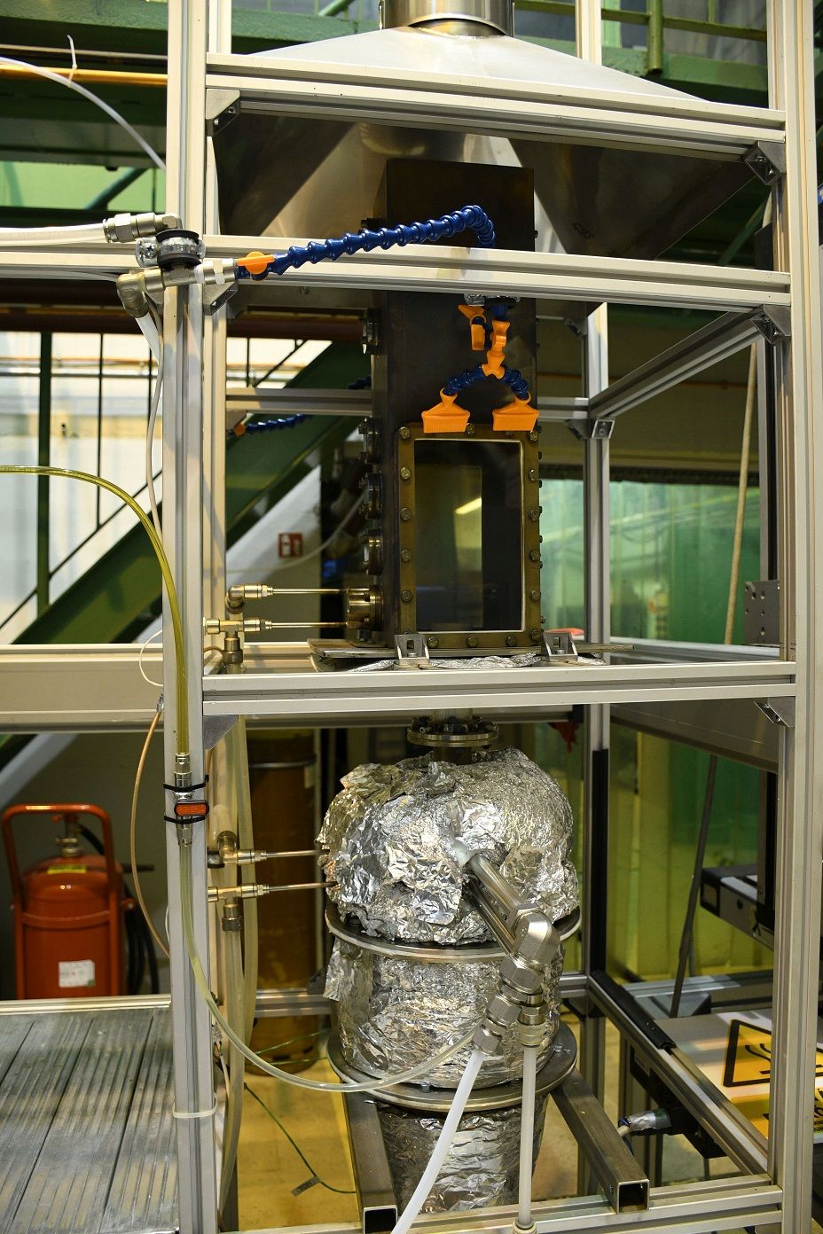
A new combustion test rig was built for a wide range of liquid and gaseous fuels, or dual-fuel combustion. Acoustic, chemiluminescence, and pollutant emission measurements are available with our instruments. Furthermore, high-speed Schlieren measurements and Phase Doppler Anemometry were performed during the summer of 2021. The instruments were brought by Dr. Milan Malý from the Brno University of Technology. The project is hosted by the George Jendrassik laboratory of Department of Energy Engineering. The construction of the test rig and its instrumentation were funded by the OTKA-FK 124704 and the 137758 grants by the National Research, Development and Innovation Office.
System completed
The combustion test rig is completed now with 100% success. A new combustion mode, Mixtrure Temperature Controlled (MTC), was discovered that delivers ultra-low emissions and distributed combustion without internal or external recirculation, which is typical for MILD combustion. We are looking forward for future tests and expanding the rig with new instruments to better understand MTC combustion and its operation since it is not predicted by any theory that it should exist under the set operating conditions. Upon a better understanding, our group will focus on its introduction to practical applications, like furnaces, boilers, and gas turbines.
20.01.2020

First systematic tests
The system integrity was stretched by a series of coconut methyl ester biodiesel test which is now evaluated and the results are prepared for publication. This is the first result that relies solely on the new combustion test rig.
14.12.2019
liquid fuel combustion is performed
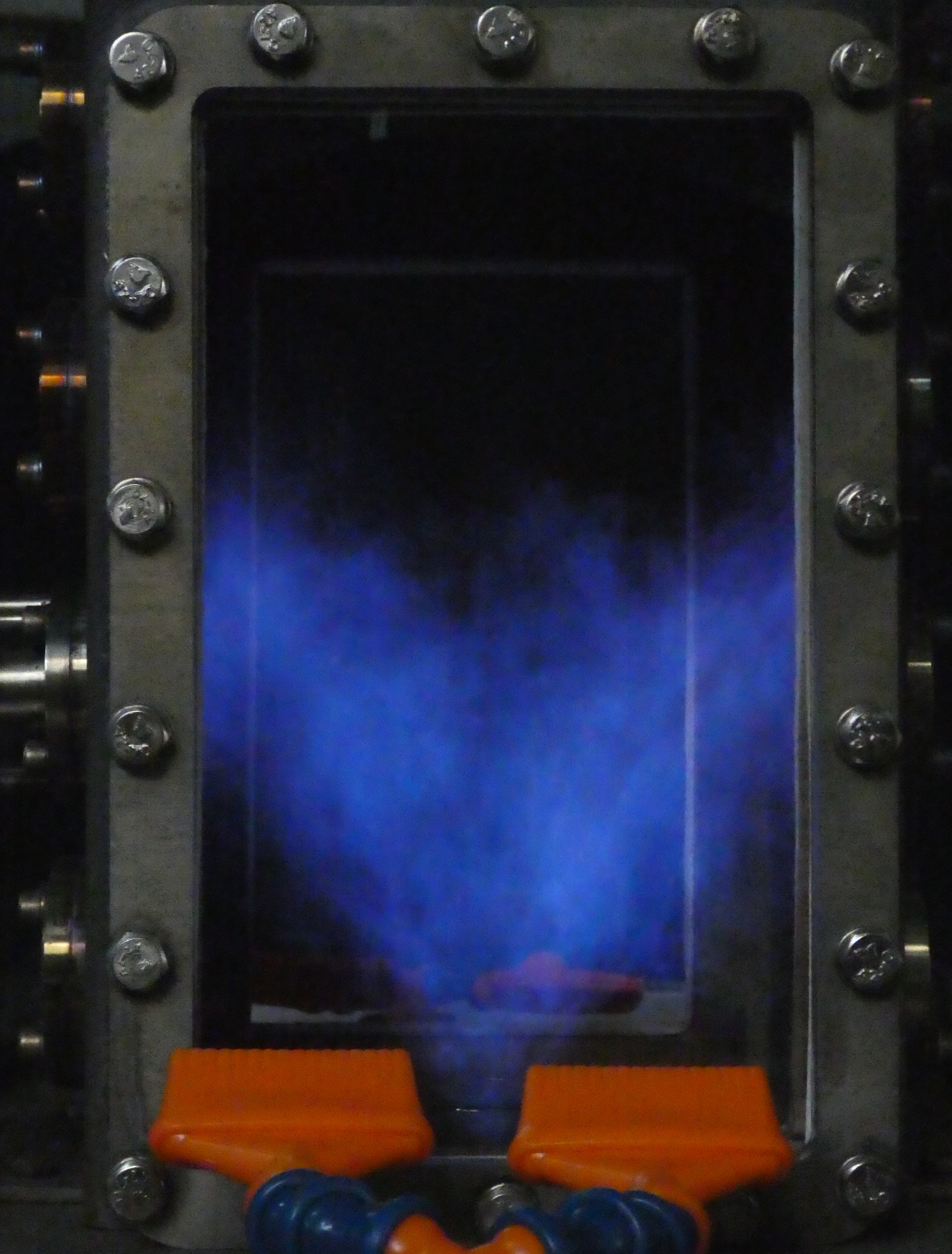
After solving all the issues in the fuel line, adding the windows and closing the combustion chamber, finally, liquid fuel combustion with diesel oil was successful. This is the most significant milestone in the system. In the next step, we will calibrate the sensors and update our data acquisition system. Then testing various renewable fuels will come.
24.10.2019
Windows were added
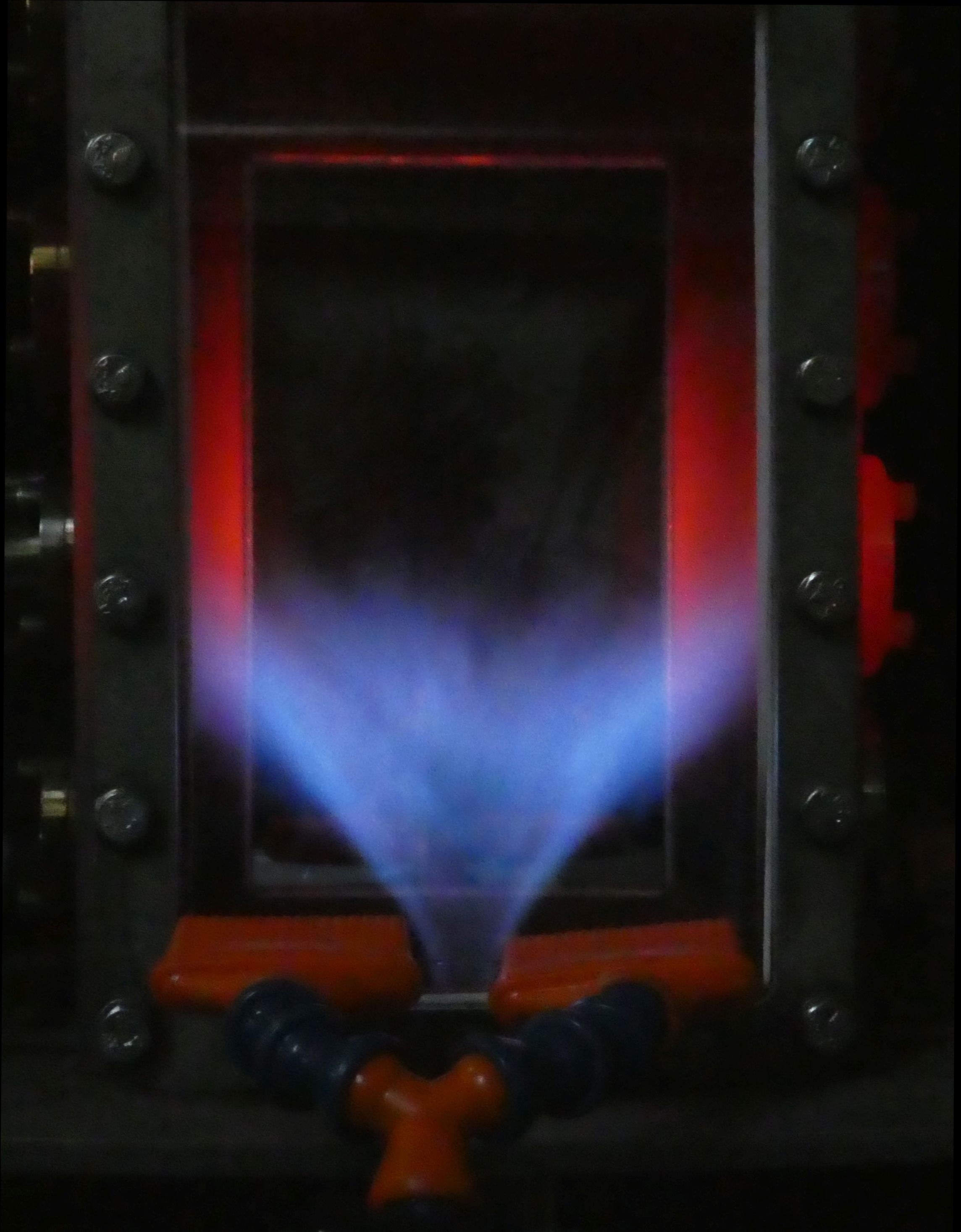
The combustion chamber window slots were empty until the operation becomes smooth, and the ignition is solved. Since the flat quartz plates are rather expensive and shipping takes a long time, we wanted to avoid any unnecessary damage to them. Interestingly, the mixing tube glasses, which are pipes, are much cheaper and locally available. The combustion conditions have been significantly changed; you can see that the chamber is glowing red, unlike in all the previous pictures. Note that the reason for asymmetrical behavior is that there is a cooled sensor socket on the left side. For evaluation, Pt100 resistance thermometers were added to it, and the system successfully withstood the hot flame next to that.
09.10.2019
The cooling system has been installed
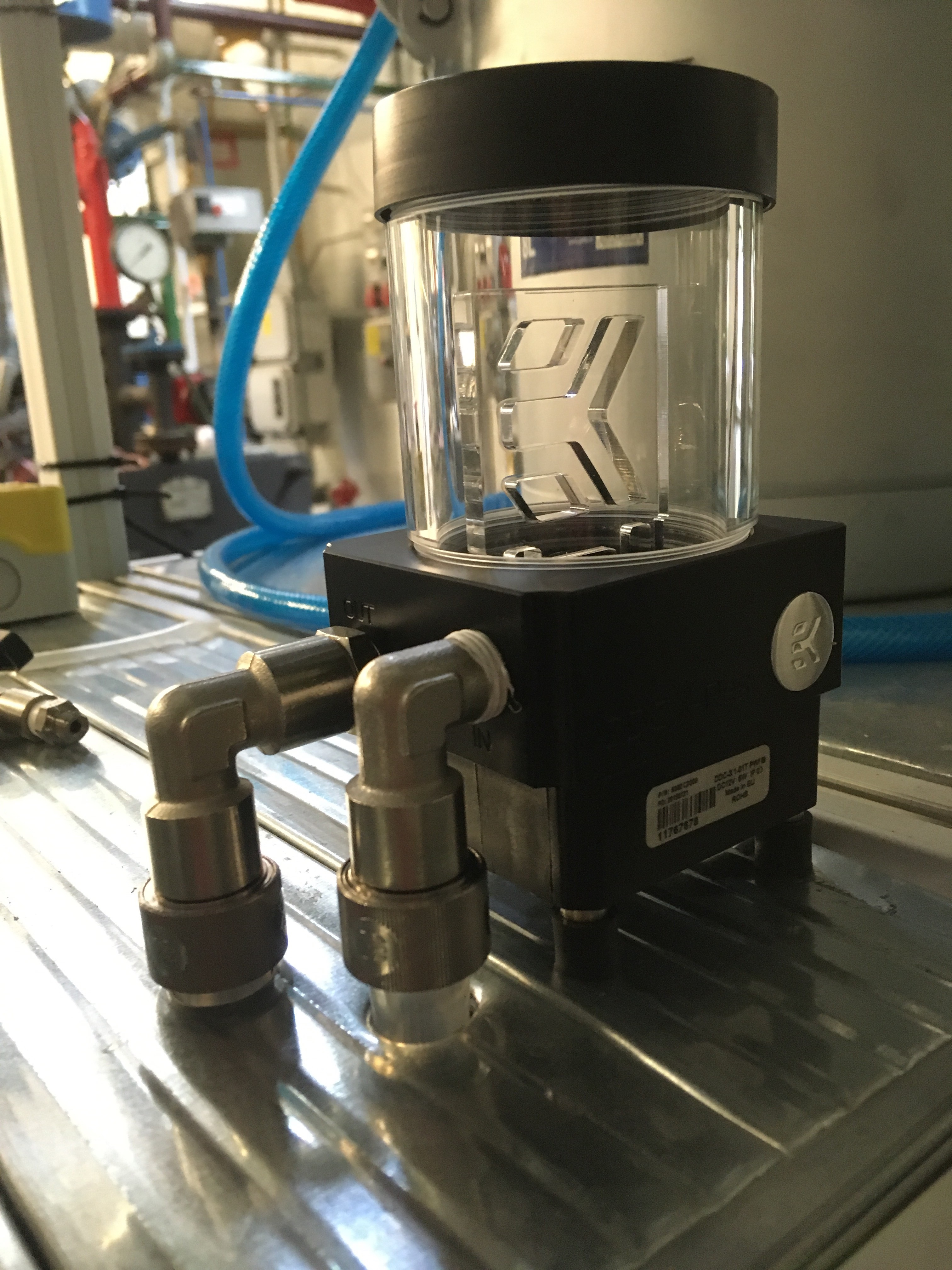
The cooling of the microphone is necessary since it withstands temperatures up to 125 °C. Hence, the designed cooled sensor socked was connected to a liquid cooling system that was originally designed for a PC. The quartz windows were still missing from the combustion chamber, however, their cooling system was also installed. The last missing item from the setup is the igniter that will be resolved soon. This is the last item that is required for full functionality.
25.09.2019
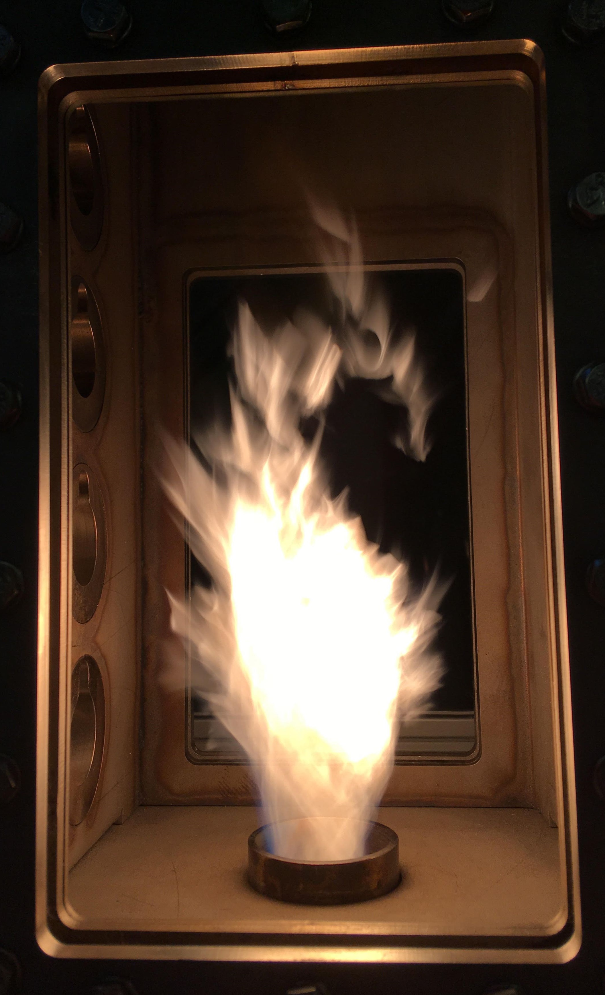
Liquid fuel combustion test is completed
Today is a turning point in the research project. We managed to test all the designed operating conditions of the new test rig. However, this is only the beginning of scientific work to be performed. All the connecting subsystems work flawlessly along with the low-frequency data acquisitions system. There are still several problems to solve, however, the modular structure allows us to work on the rig efficiently.
15.08.2019
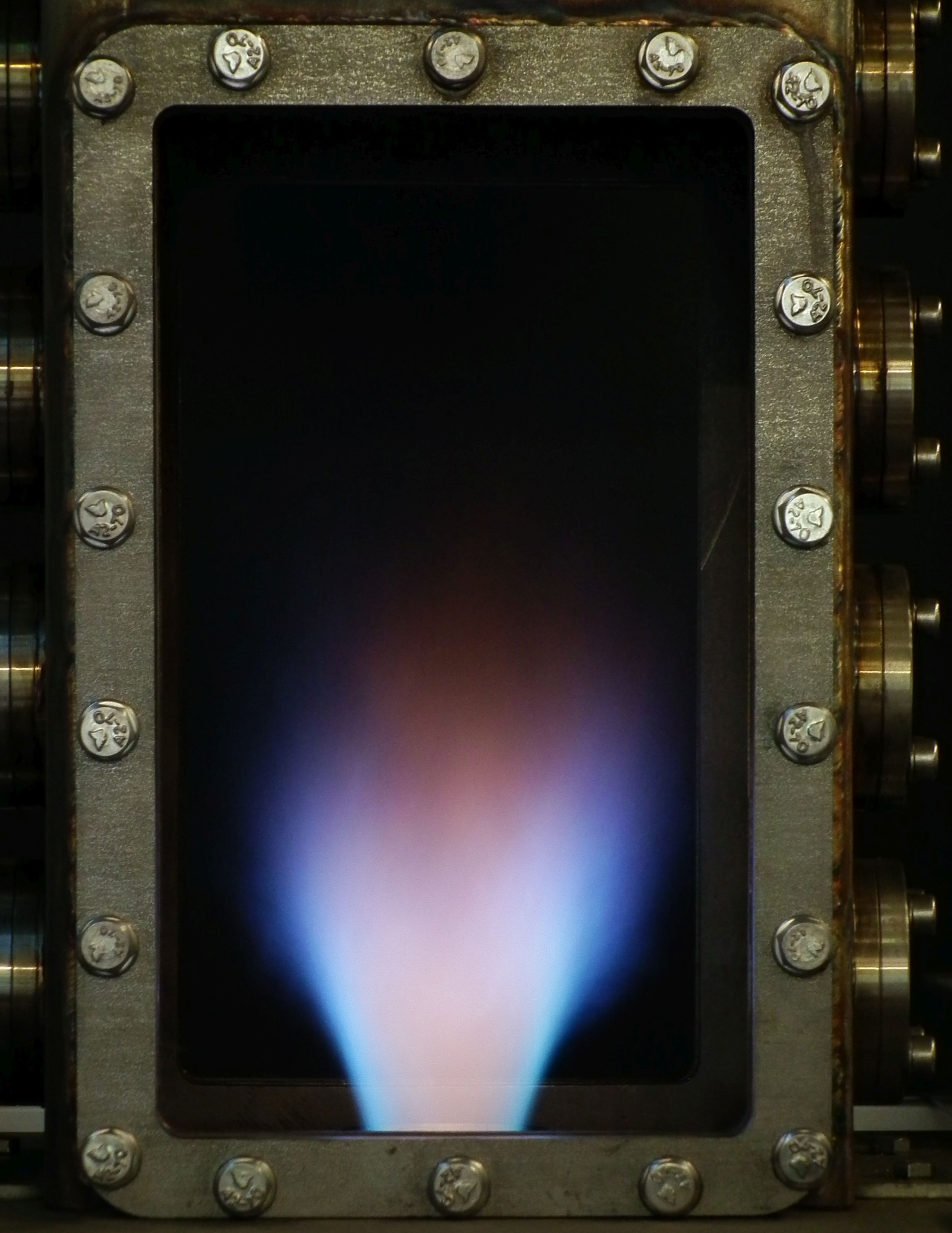
Dual fuel combustion test: done
Following the easier operation with natural gas, the system was prepared for liquid fuel combustion. As the test fuel was diesel oil, a certain extent of air preheating is necessary for smooth operation. The set temperature was only 250 °C initially, which resulted in incomplete fuel evaporation yet. However, a stable operation was achieved with the addition of ~20% natural gas. Calibration of the liquid fuel system’s sensors are under way, and a precision pressure regulator valve will replace the currently used standard variant. It is expected that the test rig will be ready for the first tests with liquid fuels by the end of this month.
08.08.2019

First successful hot test is complete
The first hot tests were successful with natural gas as fuel. Even though the picture shows a state with 18 kW thermal power instead of the desired 30 kW, the system performed otherwise flawlessly. Just before this test, the airblast atomizer also performed well with distilled water. The most difficult part of the assembly was to ensure that the central fuel pipe stays there in the small orifice and the annular atomizing medium channel is maintained.
04.06.2019
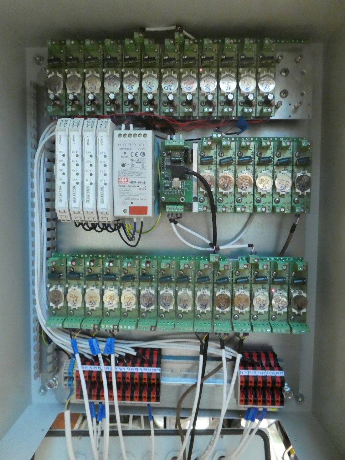
Data acquisition system is online
The measurement system consists of Pt100 resistance thermometers, T and K-type thermocouples, 4-20 mA pressure transducers, and flow meters with 4-20 mA and 0-5 V configurations. All these data will be recorded at 1 Hz since the system will operate in a steady state. This part is the low-frequency DAQ system which is responsible for controlling the environment to provide smooth intakes and record all the variables to facilitate repeatability.
05.04.2019
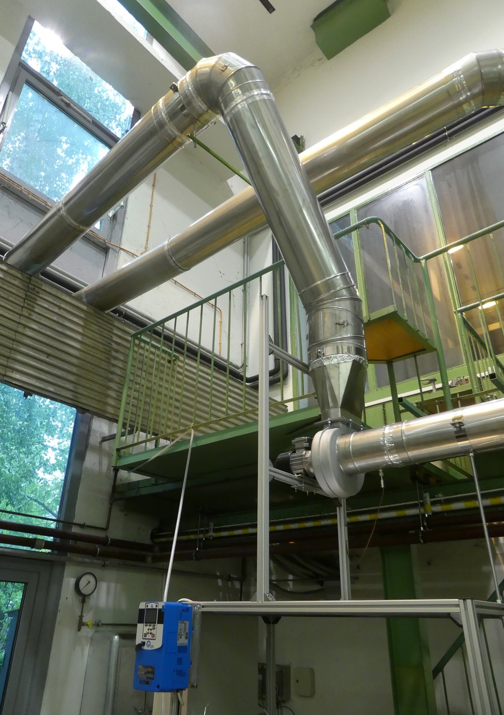
Exhaust gas system is assembled
The flue gas system is consisting of a hood which allows ambient air entrainment. This is mandatory to ensure that the hot flue gas is below 200 °C when it enters the fan. There is a thermocouple before that, and the power can be adjusted by using a frequency converter. The system ran flawlessly at the first test.
01.03.2019
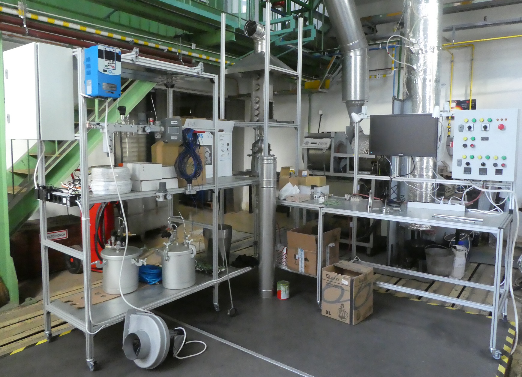
First cold test run is completed!
During the design phase, it became evident that the combustion air fan of the system is a key component which should be selected after testing the assembly. However, preceding calculations were made, the combustion air preheater is a complex device to estimate its pressure drop. Therefore, the measurement of flow characteristics required all the burner system assembled which was completed this week. Since the fan of the old test rig was big enough to surely provide the demanded flow rate, it was used to determine the design requirements of the new fan. The effect of air preheating greatly affect the pressure drop, so the combustion air temperature was increased from ambient to 400 °C in 100 °C steps. The task of the upcoming weeks will be the assembly of the flue gas system and the preparation of the burner for hot tests.
08.02.2019
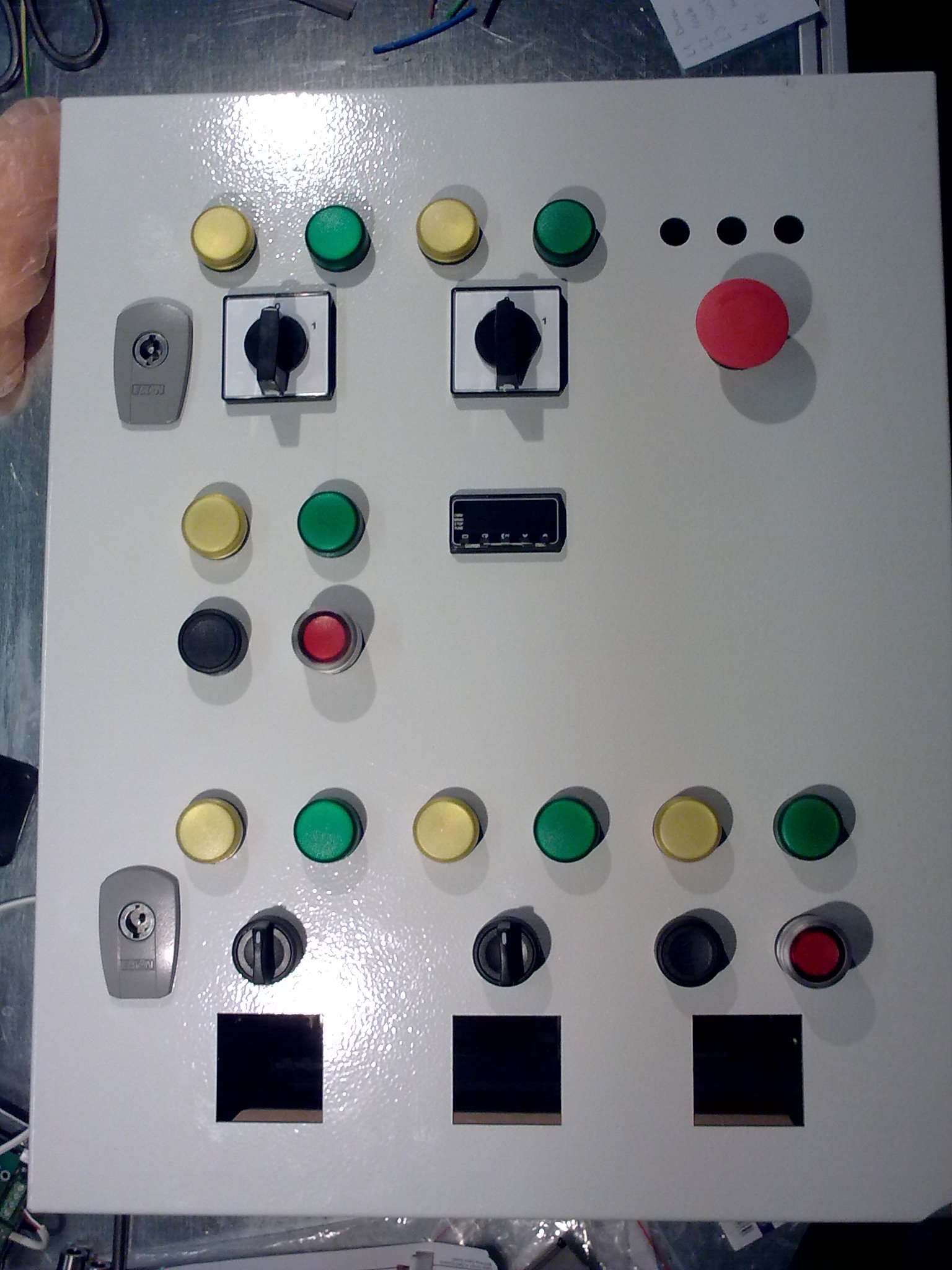
Front panel of the power electronic box is getting ready
The previous test rig required too many manual adjustments at several places by the end which required automation and simplification. We are in the middle of the electric design, and only one thing is sure. There will be numerous lamps and buttons. 🙂 The above image is just the beginning.
18.01.2019
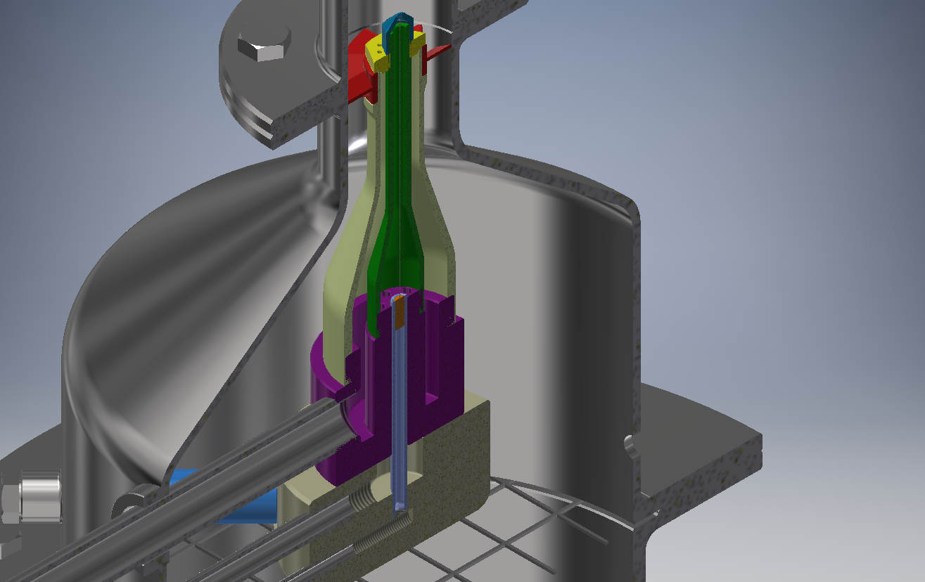
3D model of the burner is complete
The burner design is ready; now it is submitted for production. It features three inlet ports. The central one is for liquid fuels; the concentric one is for atomizing air. Even though the efficiency of plain-jet airblast atomizer is low, it is convenient for laboratory use. The third intake is responsible for setting the swirl number by injecting air through several side holes. Also, these holes may serve for gaseous fuel injection.
03.05.2018
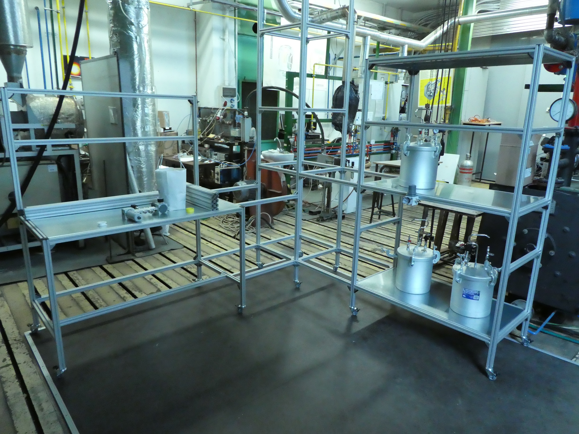
Framework is assembled
We have received the framework of the new test rig and it is now fully assembled. The core part is the burner which is under design. Until the manufacturing completes, the pneumatic and fuels systems will be prepared.
17.04.2018
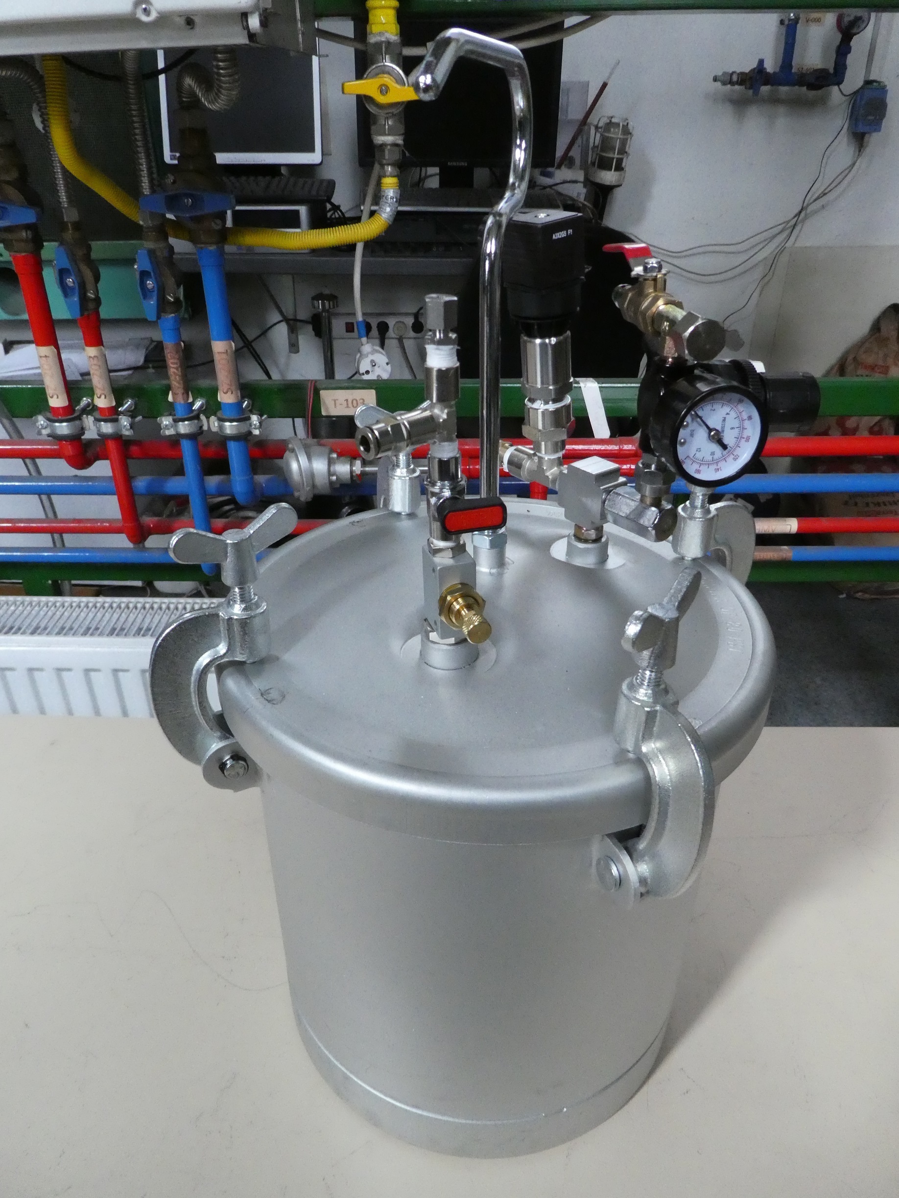
Liquid supply tank
Delivering a constant mass flow rate is quite challenging. Only volumetric pumps exist in the ~1 g/s range which generates oscillations. One solution is choking the flow, however, a more convenient way to use a pressurized tank. A needle valve performs raw adjusting while the gauge pressure does fine tuning. This simple system performed excellently through several test sessions.
